This diagram is essential for identifying the correct wire for a particular function and ensuring proper installation and connection. The ignition switch wire diagram typically includes labels for each wire, indicating its function. Common labels may include “B” for battery power, “IGN” for ignition power, “ACC” for accessory power
Starter circuit diagram | Automotive electrical, Electrical diagram, Electricity
Push button Ignition Switch Wiring Diagram . Push button Ignition Switch Wiring Diagram New. Push button Switch Wiring Diagram New Push button Switch Wiring. Simple Push button Wiring Enthusiast Wiring Diagrams •. Push button Switch Wiring Diagram 2018 Ignition Relay Wiring Diagram
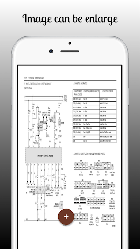
Source Image: play.google.com
Download Image
Now let’s discuss the wiring connections of a 3 position ignition switch. The specific terminals and wire colors may vary depending on the make and model of the vehicle, but here is a general overview: 1. B (Battery) Terminal: This terminal is connected to the positive side of the vehicle’s battery.

Source Image: jockeyjournal.com
Download Image
Ignition Switch Wiring Diagram] | Chevy, Chevy c10, Chevy trucks To properly wire a 4 terminal ignition switch, you will need to connect the appropriate wires to the corresponding terminals. The “B” terminal should be connected to the positive terminal of the battery, either directly or through a fuse. The “S” terminal should be connected to the starter solenoid’s activation wire.
Source Image: quora.com
Download Image
Ignition Switch Wiring Diagrams
To properly wire a 4 terminal ignition switch, you will need to connect the appropriate wires to the corresponding terminals. The “B” terminal should be connected to the positive terminal of the battery, either directly or through a fuse. The “S” terminal should be connected to the starter solenoid’s activation wire. Jan 13, 2024Step 12: Attach the Ignition Wire. Attach the ignition wire to the “IGN” terminal of the vehicle’s ignition switch. The central terminal serves the car’s ignition, wipers, accessories, and other operating features. It is essentially the default “run” position of the ignition switch.
How to wire a 4-speed fan switch – Quora
Inboard Boat Ignition Switch Wiring DiagramWelcome to our comprehensive guide on inboard boat ignition switch wiring diagrams. If you’re a boat owner or enthusiast, understanding the wiring diagram for your inboard boat’s ignition switch is essential. This diagram provides a clear visual representation of how the various components are connected and ensures proper installation Sample Basic Wiring Diagram for Small Engines using Magneto Ignition with Points – iSaveTractors
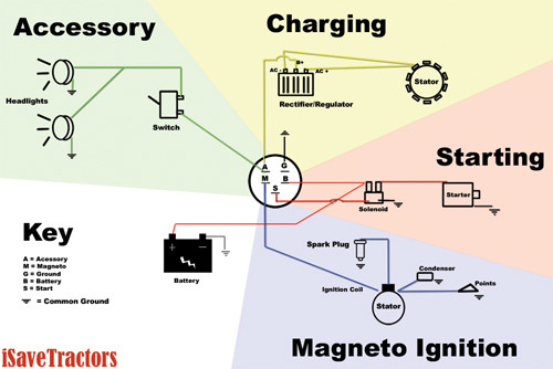
Source Image: isavetractors.com
Download Image
Non-OEM Electrical CDI Wiring for Obscure Engine – Motorcycle Engineering & Fabrication – ThumperTalk Inboard Boat Ignition Switch Wiring DiagramWelcome to our comprehensive guide on inboard boat ignition switch wiring diagrams. If you’re a boat owner or enthusiast, understanding the wiring diagram for your inboard boat’s ignition switch is essential. This diagram provides a clear visual representation of how the various components are connected and ensures proper installation
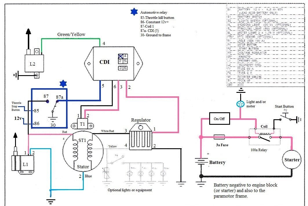
Source Image: thumpertalk.com
Download Image
Starter circuit diagram | Automotive electrical, Electrical diagram, Electricity This diagram is essential for identifying the correct wire for a particular function and ensuring proper installation and connection. The ignition switch wire diagram typically includes labels for each wire, indicating its function. Common labels may include “B” for battery power, “IGN” for ignition power, “ACC” for accessory power

Source Image: pinterest.com
Download Image
Ignition Switch Wiring Diagram] | Chevy, Chevy c10, Chevy trucks Now let’s discuss the wiring connections of a 3 position ignition switch. The specific terminals and wire colors may vary depending on the make and model of the vehicle, but here is a general overview: 1. B (Battery) Terminal: This terminal is connected to the positive side of the vehicle’s battery.
![Ignition Switch Wiring Diagram] | Chevy, Chevy c10, Chevy trucks](https://i.pinimg.com/564x/63/71/78/6371789240bcd6207e49acd0b704315d.jpg)
Source Image: pinterest.com
Download Image
gm steering column wiring diagram | GM Steering Column Wiring – Rat Rod Nation – Rat Rod, Rat Rods | Rat rod, Steering column, Column **PARTS LIST IN DESCRIPTION BELOW**Adding a push button start ignition to a race car is pretty darn cool, and these days you can easily buy all the parts you

Source Image: pinterest.com
Download Image
What Are The Ignition Switch Wiring Color Codes? 3 | Color coding, Wire switch, Switch To properly wire a 4 terminal ignition switch, you will need to connect the appropriate wires to the corresponding terminals. The “B” terminal should be connected to the positive terminal of the battery, either directly or through a fuse. The “S” terminal should be connected to the starter solenoid’s activation wire.

Source Image: pinterest.com
Download Image
Marine Ignition Switch Wiring Diagram | Mercury outboard, Electrical wiring diagram, Outboard boat motors Jan 13, 2024Step 12: Attach the Ignition Wire. Attach the ignition wire to the “IGN” terminal of the vehicle’s ignition switch. The central terminal serves the car’s ignition, wipers, accessories, and other operating features. It is essentially the default “run” position of the ignition switch.

Source Image: pinterest.com
Download Image
Non-OEM Electrical CDI Wiring for Obscure Engine – Motorcycle Engineering & Fabrication – ThumperTalk
Marine Ignition Switch Wiring Diagram | Mercury outboard, Electrical wiring diagram, Outboard boat motors Push button Ignition Switch Wiring Diagram . Push button Ignition Switch Wiring Diagram New. Push button Switch Wiring Diagram New Push button Switch Wiring. Simple Push button Wiring Enthusiast Wiring Diagrams •. Push button Switch Wiring Diagram 2018 Ignition Relay Wiring Diagram
Ignition Switch Wiring Diagram] | Chevy, Chevy c10, Chevy trucks What Are The Ignition Switch Wiring Color Codes? 3 | Color coding, Wire switch, Switch **PARTS LIST IN DESCRIPTION BELOW**Adding a push button start ignition to a race car is pretty darn cool, and these days you can easily buy all the parts you

